Sensor, Tire Pressure Monitoring (TPM): Installation: SRT8
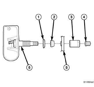
Before reinstalling an existing tire pressure sensor, replace seal (2) and metal washer (1) at base of sensor valve stem (6) to ensure proper sealing.
- Wipe area clean around sensor/valve stem mounting hole in wheel (5). Make sure surface of wheel is not damaged.CAUTION:
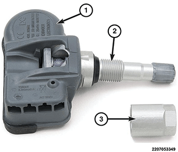
To avoid damaging sensor antenna strap (1), if equipped, hold pressure against rear of metal valve stem (2) while sensor is inserted through wheel mounting hole and nut is installed.
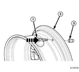
- Insert sensor (1) through wheel (2) as shown in the illustration keeping pressure against rear of metal valve stem (See Arrow). Potted side of sensor is to be positioned toward wheel. Do not attempt to mount sensor otherwise, damage may occur.
- Install sensor nut (with pressed-in washer) (3) by hand.CAUTION:
Over-torquing the sensor nut by as little as 12 N.m (106 in. lbs.) may result in sensor separation from the valve stem. Under this condition, the sensor may still function. However, the condition should be corrected immediately.
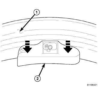
NOTE:Before tightening sensor nut, push downward on sensor housing (2) in an attempt to make it flush with interior contour of wheel (1).
- While holding sensor in position, tighten sensor nut to the proper torque specifications. Refer to TORQUE SPECIFICATIONS .
- Mount tire on wheel following tire changer manufacturers instructions, paying special attention to the following to avoid damaging tire pressure sensor:
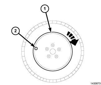
Rotating Wheel Tire Changers - Once the wheel is mounted to the changer, position the sensor valve stem (2) approximately 280° from the head of the changer (located at 1) in a clockwise direction before rotating the wheel (also in a clockwise direction) to mount the tire. Use this procedure on both the outer and inner tire beads.
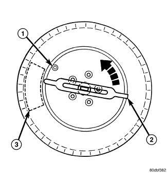
Rotating Tool Tire Changers - Position the wheel on the changer so that the sensor valve stem (1) is located approximately 210° clockwise from the installation end of the mounting/dismounting tool (2) once the tool is mounted for tire installation. Make sure the sensor is clear of the lower bead breaker area (3) to avoid damaging the sensor when the breaker rises. Rotate the tool (2) in a counterclockwise direction to mount the tire. Use this procedure on both the outer and inner tire beads.
- Adjust air pressure to that listed on Tire Inflation Pressure Label (Placard) provided with vehicle (usually applied to driver's side B-pillar). Make sure original style valve stem cap is securely installed to keep moisture out of sensor.
- Install tire and wheel assembly on vehicle.
- Remove the support and lower the vehicle.
- Perform one of the following to make the system learn the new sensor ID.
- Using the TPM-RKE Analyzer 9936 with the Scan Tool, program the TPM Module with the new tire pressure sensor ID. This is part of the TPM Diagnostic Verification Test. Refer to STANDARD PROCEDURE .
- The vehicle should remain stationary for at least 20 minutes. Drive the vehicle for a minimum of 20 minutes while maintaining a continuous speed above 24 km/h (15 mph). During this time, the system will recognize and add the new sensor ID. This is part of the TPM Diagnostic Verification Test. Refer to STANDARD PROCEDURE .
If a sensor cannot be trained, refer to appropriate diagnostic information.