Isolator, Rear CROSSMEMBER, Rear Mount: Removal
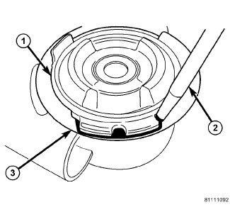
| 1 - BUSHING CAN FLANGE |
| 2 - MARKER OR CRAYON |
| 3 - CROSSMEMBER |
- Remove the rear crossmember. Refer to CROSSMEMBER, REAR, REMOVAL .
- As an installation reference, carefully mark location of bushing requiring removal on crossmember (around bushing can flange) using a marker or crayon. Do not use a scratch awl to mark location.
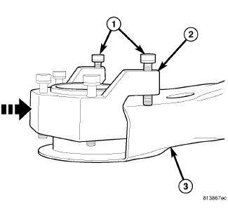
- Slide Support (2), Special Tool (special tool #9031-11, Clamp), into end of crossmember (3) surrounding bushing bore as shown in illustration.
- Snug set-screws (1) securing Support (2) to crossmember.
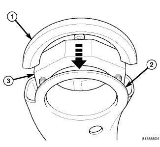
- Insert Brace (1), Special Tool (special tool #9031-12, Brace), between Support (special tool #9031-11, Clamp) (3) and bushing bore flange (2) matching angle cut in Brace to bore flange.
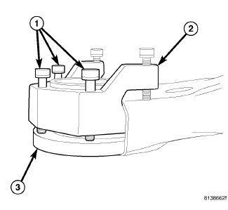
- Snug set-screws (1) against Brace (special tool #9031-12, Brace). Do not overtighten set-screws as they will distort and bend bushing bore flange. NOTE:
Prior to using Press (1), Special Tool (special tool #C-4212F, Press, Ball Joint), lubricate screw-drive threads to provide ease of use and promote tool longevity.
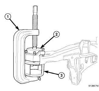
- Assemble tools (See following list) over bushing as shown in illustration.
- (1) Press (special tool #C-4212F, Press, Ball Joint)
- (2) Remover (special tool #9031-2, Remover, Bushing)
- (3) Receiver (special tool #9031-1, Bushing Removal Receiver)
- Tighten Press (1) screw-drive, pressing bushing out of crossmember.
- Remove all tools.