Diagnostic Test
- CHECK THE ANTENNA CONNECTION
- Turn the ignition off.
- Disconnect the AM/FM Audio Antenna white connector at the rear of the Radio (RRM).
- Inspect the Audio Antenna connection.
Is the Antenna connection clean and secure?
Yes
- Go To 2
No
- Repair the Antenna connection as needed.
- Perform the BODY VERIFICATION TEST. Refer to BODY VERIFICATION TEST .
- CHECK THE RADIO
- Connect the (special tool #9977-6-FM, Antenna) to the antenna connection on the back of the Radio.
- Place the magnetic test antenna on the roof of the vehicle.
- Turn the ignition on.
- Turn the Radio on and set it to AM or FM band.
- Tune in to several AM and FM stations.
- Note any of the following type of reception concerns being heard:
- Silence
- Static
- Noise
- Popping
- Screeching
- Hissing
- Crackling
- Humming
- Weak Signal
- Interference
- Motor Sound
Is the audio reception still poor or not available?
Yes
- Replace the Radio in accordance to the service information. Refer to RADIO, REMOVAL .
- Perform the BODY VERIFICATION TEST. Refer to BODY VERIFICATION TEST .
No
- Go To 3
- TEST THE ANTENNA MODULE AND GRID
- Turn the ignition off.
- Disconnect the test antenna and connect the harness connector to the Radio.
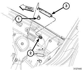
- Remove the right C-Pillar trim to gain access to the Antenna Module (3). Refer to PANEL, C-PILLAR TRIM, REMOVAL . Remove the mounting bolt holding the Antenna Module (1).
- Disconnect the white AM/FM antenna cable connector (2) from the antenna module.
- Connect the (special tool #9977-6-FM, Antenna) to the white AM/FM antenna cable harness connector.
- Turn the ignition on.
- Turn the Radio on and set it to AM or FM band.
- Tune in to several AM and FM stations.
- Note any of the following type of reception concerns being heard:
- Silence
- Static
- Noise
- Popping
- Screeching
- Hissing
- Crackling
- Humming
- Weak Signal
- Interference
- Motor Sound
Is the audio reception still poor or not available?
Yes
- Go To 4
No
- Check the antenna grid and repair if necessary. Refer to MAST, ANTENNA, DIAGNOSIS AND TESTING . If the grid checks good, replace the Antenna Module in accordance with the Service Information.
- TEST THE ANTENNA CABLE
- Turn the ignition off.
- Disconnect the (special tool #9977-6-FM, Antenna) from the Antenna cable.
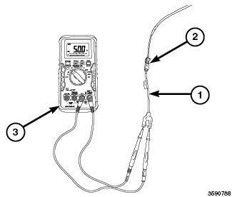
- Connect the appropriate 50 Ohm test (special tool #9977-6-4, Jumper) (1) or (special tool #9977-6-2, Jumper) (1) to the Antenna cable (2) at the Antenna Module harness connector.
- Disconnect the AM/FM Audio Antenna white connector at the rear of the Radio.
- Connect the appropriate (special tool #9977-6-1, Adapter) (1) or (special tool #9977-6-3, Adapter) (1) to the antenna cable (2) at the back of the Radio.
- Measure the Resistance across the tool terminals.
Is the resistance above 52.5 or below 47.5 Ohms?
Yes
- Go To 5
No
- The source of the poor reception is not caused by the Radio or the Antenna cable. Re-check the antenna grid and repair if necessary. Refer to MAST, ANTENNA, DIAGNOSIS AND TESTING . If the grid checks good, replace the Antenna Module in accordance with the Service Information.
- Perform the BODY VERIFICATION TEST. Refer to BODY VERIFICATION TEST .
- TEST THE ANTENNA CABLE FROM THE RADIO TO INLINE CONNECTOR
- Disconnect the appropriate (special tool #9977-6-4, Jumper) or (special tool #9977-6-2, Jumper) from the antenna cable at the Antenna Module connector.
- Remove the Glove Box Assembly. Refer to GLOVE BOX, INSTRUMENT PANEL, REMOVAL .
- Disconnect the white AM/FM antenna connector mounted on the blower housing.
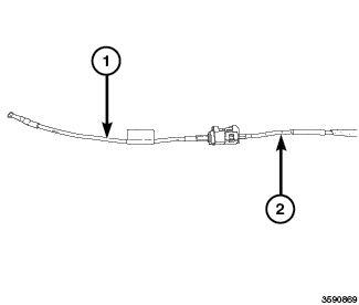
- Connect the appropriate 50 Ohm test (special tool #9977-6-4, Jumper) (1) or (special tool #9977-6-2, Jumper) (2) to the side of the Antenna cable (2) that leads to the Radio.
- Measure the Resistance across the tool terminals.
Is the resistance above 52.5 or below 47.5 Ohms?
Yes
- Replace the section of antenna cable from the Radio to inline connector.
- Perform the BODY VERIFICATION TEST. Refer to BODY VERIFICATION TEST .
No
- Go To 6
- TEST THE ANTENNA CABLE FROM THE INLINE CONNECTOR TO THE ANTENNA MODULE
- Disconnect the appropriate (special tool #9977-6-1, Adapter) or (special tool #9977-6-3, Adapter) from the rear of the Radio.
- Connect the appropriate (special tool #9977-6-1, Adapter) (1) or (special tool #9977-6-3, Adapter) (1) to the Antenna cable (2) at the Antenna Module connector.
- Measure the resistance across the tool terminals.
Is the resistance above 52.5 or below 47.5 Ohms?
Yes
- Replace the section of antenna cable from the inline connector to the Antenna Module.
- Perform the BODY VERIFICATION TEST. Refer to BODY VERIFICATION TEST .
No
- The source of the poor reception is not caused by the Radio or the Antenna cable. Re-check the antenna grid and repair if necessary. Refer to MAST, ANTENNA, DIAGNOSIS AND TESTING . If the grid checks good, replace the antenna module in accordance with the Service Information.
- Perform the BODY VERIFICATION TEST. Refer to BODY VERIFICATION TEST .