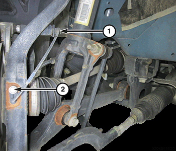
Knuckle, Steering, AWD: Installation
NOTE:
Left side shown in illustration, right side similar.
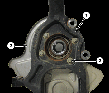
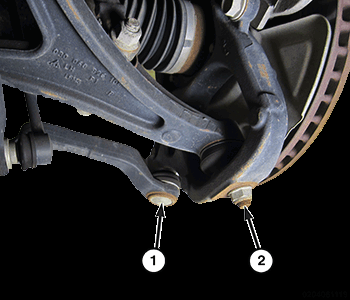
- If hub and bearing and dust shield needs to be installed on knuckle, perform following:
- Slide shield (3) onto rear of hub and bearing.
- Slide hub and bearing into knuckle (1), lining up mounting holes in hub and bearing with those in shield and knuckle.
- Install the four hub and bearing to knuckle bolts (2), and tighten bolts to the proper torque specifications. Refer to TORQUE SPECIFICATIONS .
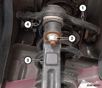
- Place knuckle over lower ball joint stud and guide hub and bearing onto axle half shaft.
- Start NEW
lower control arm to knuckle nut (2). Do not tighten at this time. CAUTION:
It is important to tighten nut as described in following step to avoid damaging ball stud joint.
- Install the upper ball joint through the knuckle, and tighten the upper control arm to knuckle nut to the proper torque specifications. Refer to TORQUE SPECIFICATIONS .CAUTION:
It is important to tighten nut as described in following step to avoid damaging ball stud joint.
- Tighten lower control arm to knuckle nut (4). Tighten to the proper torque specifications. Refer to TORQUE SPECIFICATIONS .CAUTION:
It is important to tighten nut as described in following step to avoid damaging ball stud joint.
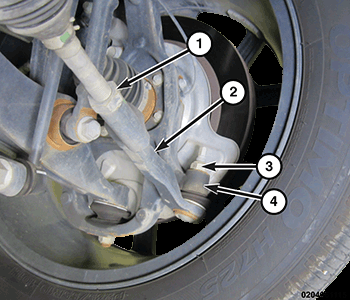
- Install the outer tie rod end (2) through the knuckle (4), and tighten nut to the proper torque specifications. Refer to TORQUE SPECIFICATIONS .
- Install brake rotor, then disc brake caliper and adapter assembly. Refer to ROTOR, BRAKE, INSTALLATION
.NOTE:
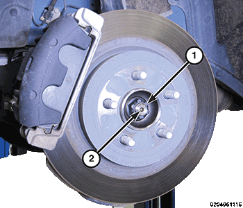
Always install a NEW hub nut. The original hub nut is one-time use only and should be discarded when removed.
- Install hub nut (1) on end of axle half shaft (2). While a helper applies brakes to keep hub from turning, tighten hub nut to the proper torque specifications. Refer to TORQUE SPECIFICATIONS .
- Install wheel speed sensor head into knuckle and install wheel speed sensor to knuckle screw (2), and tighten screw to the proper torque specifications. Refer to TORQUE SPECIFICATIONS .
- Attach wheel speed sensor cable routing clip (1) to the knuckle.
- Install the tire and wheel assembly. Refer to INSTALLATION .
- Remove the support and lower the vehicle.
- Pump brake pedal several times to ensure vehicle has a firm brake pedal before moving vehicle.
- Check and adjust brake fluid level in reservoir as necessary.
- Perform wheel alignment. Refer to WHEEL ALIGNMENT, STANDARD PROCEDURE .