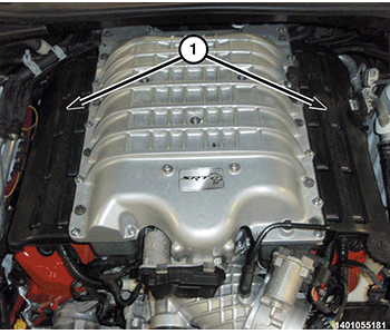
Cooler, Charge Air: Installation
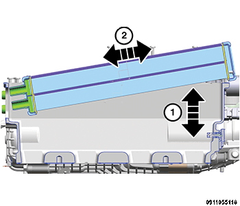
- Insert the coolers into the rotor case (2) and gently position the coolers inside the rotor case (1).
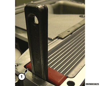
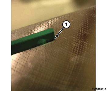
- Insert wedges (1) between the front side of the rotor case and the cooler to prevent the cooler from sliding out of position.
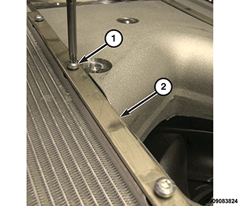
- Place the isolation bars (2) into position and hand tighten the retaining screws (1).
- Using a non-petroleum based lubricant, lubricate the cooler O-rings and the O-ring pockets of the coolant crossover manifold.
- Insert the NEW coolant crossover seals into the rotor case and carefully place the coolant crossover manifold back into place.
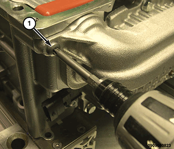
- Tighten the coolant crossover retaining screws (1) to the proper torque specifications. Refer to 6.2L TORQUE SPECIFICATIONS .
- Tighten the isolator bar retaining screws to the proper torque specifications. Refer to 6.2L TORQUE SPECIFICATIONS .
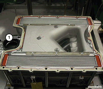
- Install a NEW
lid gasket (1) onto the supercharger.
- Install the NEW bypass and cooler retention seals in the rotor case.
- Verify that the bypass and cooler retention seals are properly seated (1) within the lid.
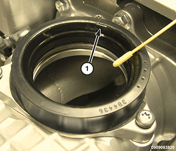
- Lubricate the bypass adapter cuff using clean engine oil (1).
- Align the lid onto the supercharger.
- Press the lid, above the bypass throttle body, into the cuff. The bypass throttle body will be partially seated in the cuff.
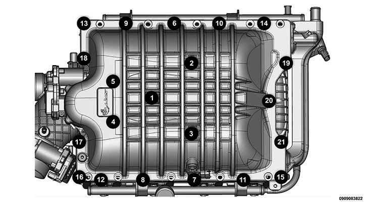
- Using the sequence shown in the illustration, tighten the retaining screws to 10 N.m (7 ft. lbs.).
- Using the sequence shown in the illustration, torque the five long lid fasteners 1-5 again, to 10 N.m (7 ft. lbs.).
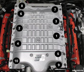
- Using the sequence shown in the illustration, Install the supercharger retaining bolts and tighten all retaining bolts as follows:
- First tighten all bolts, using the sequence, to 5 N.m (4 ft. lbs.).
- Next tighten all bolts, using the sequence, to 15 N.m (11 ft. lbs.).
- Finally tighten all bolts, using the sequence, to 30 N.m (22 ft. lbs.).
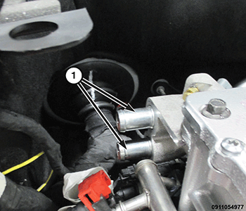
- Install the Low Temperature Radiator (LTR) circuit hoses to coolant crossover (1).
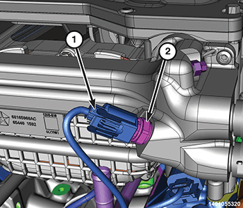
- Connect the charger air cooler temperature sensor (2) wire harness connector (1).
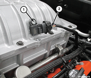
- Connect the wire harness connector (2) to the intermediate TMAP sensor (1).
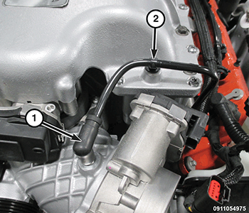
- Install the fuel purge hose (2) to the top of the supercharger nose (1).
- Install the engine covers.
- Install the cowl cover panel. Refer to COVER, COWL PANEL, INSTALLATION .
- Fill the cooling system. Refer to STANDARD PROCEDURE .NOTE:
Evacuating or purging air from the charge air cooling system must be done with the use of a pressurized air operated vacuum generator.
- Connect the negative battery cable.