Rotor RUNOUT
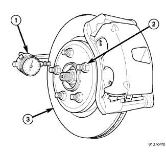
On-vehicle rotor runout is the combination of the individual runout of the hub face and the runout of the brake rotor (hub runout can be measured separately). To measure rotor runout on the vehicle:
- Raise and support the vehicle. Refer to HOISTING, STANDARD PROCEDURE .
- Remove tire and wheel assembly. Refer to REMOVAL .
- Install standard wheel mounting nuts, flat side to rotor, on all studs (2). Progressively tighten nuts to 150 N.m (110 ft. lbs.).
- Mount Dial Indicator (special tool #C-3339A, Set, Dial Indicator) (1), with Wheel, (special tool #25-W, Roller Contact Point), or equivalent, to knuckle. Position Dial Indicator Wheel to contact rotor braking surface approximately ten millimeters from outer edge of rotor (3).
- Slowly rotate brake rotor checking lateral runout, marking the low and high spots. Record these measurements.
- Check and record runout of opposite side of rotor in same fashion, marking the low and high spots.
- Compare runout measurement to specifications. Refer to ROTOR, BRAKE, SPECIFICATIONS .
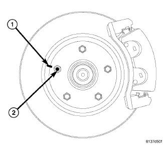
If runout is in excess of specifications, check the lateral runout of the hub face. Before removing the rotor from the hub, place a chalk mark across both the rotor (1) and the one wheel stud (2) closest to where the high runout measurement was taken. This way, the original mounting spot of the rotor on the hub is indexed.
- Remove the rotor from the hub. Refer to ROTOR, BRAKE, REMOVAL .NOTE:
Before measuring hub runout, clean the hub face surface with an appropriate cleaner. This provides a clean surface to get an accurate indicator reading.
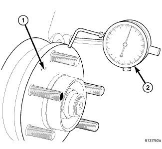
- Mount Dial Indicator (special tool #C-3339A, Set, Dial Indicator) (2), to the knuckle. Position Dial Indicator stem so it contacts hub face (1) near outer diameter. Care must be taken to position stem outside of stud circle, but inside of chamfer on the hub rim.
- Slowly rotate hub measuring runout. Hub runout should not exceed 0.01 mm (0.0004 inch). If runout exceeds this specification, the hub must be replaced. Refer to HUB AND BEARING, REMOVAL
.
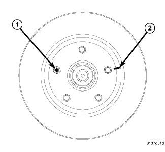
- If hub runout does not exceed this specification, install original rotor back on hub, aligning chalk mark on rotor (2) with a wheel mounting stud, two studs apart from original stud (1).
- Tighten the lug nuts to the proper torque specifications. Refer to TORQUE SPECIFICATIONS .
- Mount Dial Indicator (1) and remeasure runout on both sides of the brake rotor as explained in earlier steps to see if runout is now within specifications. Refer to ROTOR, BRAKE, SPECIFICATIONS .
- If runout is still not within specifications, reface or replace brake rotor. Refer to ROTOR, BRAKE, STANDARD PROCEDURE .