Engine Mount Isolators
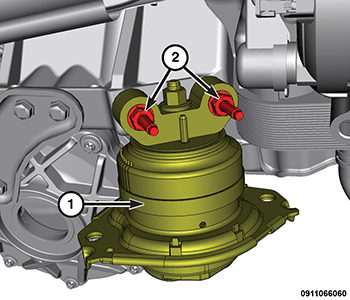
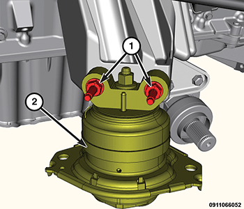
- Position the right side engine mount isolator (1), install the retaining bolts (2) and tighten to the proper specification. Refer to TORQUE SPECIFICATIONS
.
- Position the left side engine mount isolator (2), install the retaining bolts (1) and tighten to the proper specification. Refer to TORQUE SPECIFICATIONS .
- Lower the vehicle.
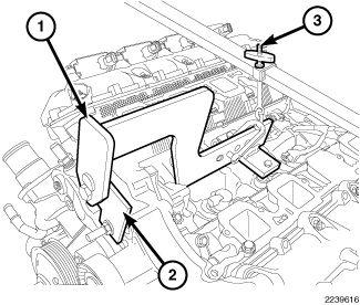
- Using the Engine Lift Fixture (special tool #8984B, Fixture, Engine Lifting) (1), Engine Lift Adapter (special tool #8984-UPD, Adapter, Engine Lift) (2) and the Engine Support Fixture (special tool #8534C, Fixture, Driveline Support) (3), lower the engine until the engine mounts are seated onto the engine cradle.
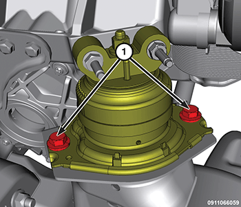
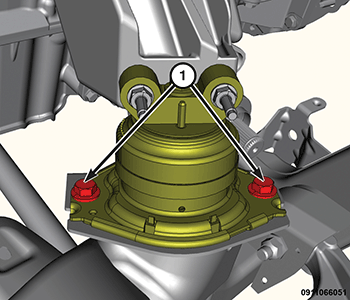
- Install the right side engine mount isolator to engine cradle retaining bolts (1) and tighten to the proper specification. Refer to TORQUE SPECIFICATIONS
.
- Install the left side engine mount isolator to engine cradle retaining bolts (1) and tighten to the proper specification. Refer to TORQUE SPECIFICATIONS
.
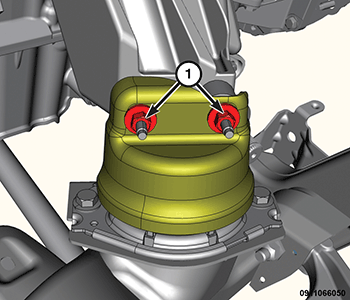
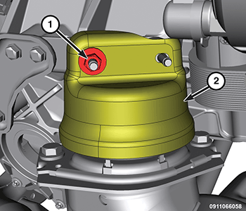
- Position the left side engine mount heat shield, install the retaining nuts (1) and tighten to the proper specification. Refer to TORQUE SPECIFICATIONS
.
- Position the right side engine mount heat shield, install the retaining nut (1) and tighten to the proper specification. Refer to TORQUE SPECIFICATIONS
.
- Raise and support the vehicle. Refer to HOISTING, STANDARD PROCEDURE .
- Install the engine oil filter. Refer to FILTER, ENGINE OIL, INSTALLATION .
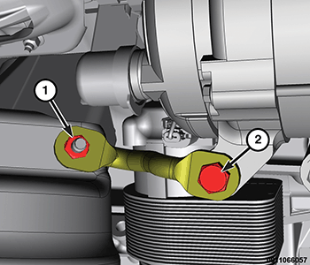
- Position the generator support bracket, install the engine mount isolator retaining nut (1) finger tight.
- Install the generator support bracket retaining bolt (2) and tighten to the proper specification. Refer to TORQUE SPECIFICATIONS .
- Tighten the generator support bracket to engine mount isolator retaining nut (1) to the proper specification. Refer to TORQUE SPECIFICATIONS .
- Install both left/right front axle half shafts. Refer to INSTALLATION .
- Install the belly pan. Refer to BELLY PAN, INSTALLATION .
- Position the engine oil dipstick tube and securely tighten the retaining nut at the exhaust manifold.
- Install the Variable Valve Timing Solenoid (VVTS). Refer to SOLENOID, VARIABLE VALVE TIMING (VVTS), EXHAUST, INSTALLATION .
- Connect the negative battery cable.