Section 2 (6.4L Engine (Service Information)): Installation
If the engine encounters a catastrophic failure, the engine oil cooler and lines must be replaced or damage to the new engine or components could result.
If the original engine has experienced a catastrophic failure or an individual failure with the piston, cylinder bore, engine block, valve or valve seat, the intake manifold MUST be replaced with a new manifold.
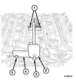
Do not use air tools to install (special tool #8984B, Fixture, Engine Lifting) (2, 3).
- Install the engine lift fixture (2) (special tool #8984B, Fixture, Engine Lifting) and adapter (special tool #8984-UPD, Adapter, Engine Lift) (4).
- Using a suitable engine hoist, lower the engine into the engine compartment.
- Automatic transmission equipped vehicles, align the engine with the transmission.
- Install two transmission bell housing to engine block bolts finger tight.
- Lower the engine assembly until the engine mounts rest in the engine cradle crossmember.
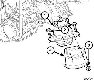
- Align the engine mounts, install both left/right engine mount to frame retaining bolts (2) and tighten to the proper specification. Refer to TORQUE SPECIFICATIONS .
- Position both left and right engine mount heat shields (4), install the retaining nuts (3) and tighten to the proper specification. Refer to TORQUE SPECIFICATIONS .
- Remove the engine hoist and the jack supporting the transmission.
- Raise and support the vehicle. Refer to HOISTING, STANDARD PROCEDURE .
- For automatic transmission equipped vehicles, follow steps 12-18.
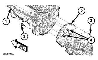
- Carefully engage transmission to engine block dowels until converter hub is seated in crankshaft. Verify that no wires, or the transmission vent hose, have become trapped between the engine block and the transmission.
- Install two bolts to attach the transmission to the engine.
- Install remaining torque converter housing to engine bolts (3 and 4). Tighten all torque converter housing bolts to the proper specification. Refer to TORQUE SPECIFICATIONS
.
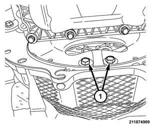
- Install all torque converter bolts (1) by hand first. There are 3 sets of two bolts 120° apart.
- Tighten all torque converter bolts to the proper specification. Refer to TORQUE SPECIFICATIONS
.
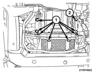
- Install the engine structural cover and tighten the bolts (1) to the proper Refer to TORQUE SPECIFICATIONS
.NOTE:
The left front structural cover bolt (2) must be installed with the cover.
- Install the starter. Refer to STARTER, INSTALLATION, 5.7L / 6.4L
.NOTE:
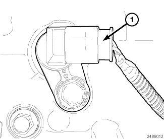
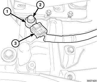
The Crankshaft Position (CKP) sensor is located at the right rear side of the engine block.
- Connect the CKP sensor wire harness connector (1).
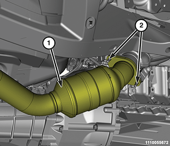
- Position the catalytic converters (1) onto the exhaust manifold flanges, install the flange nuts (2) and tighten to the proper specification. Refer to TORQUE SPECIFICATIONS
.
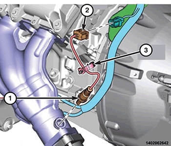
- Connect the oxygen sensor (1) wire harness connectors (2).
- Connect the right and left knock sensor (1) wire harness connectors (5).
- Install the heat shields onto both knock sensors (shield snaps on/off sensor).
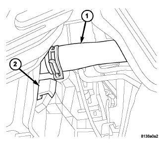
- Connect the transmission oil cooler lines to their retainers at the oil pan.
- Install the lower radiator hose (1).
- Lower the vehicle.
- Remove the engine lift fixture (special tool #8984B, Fixture, Engine Lifting) (2) and adapter (special tool #8984-UPD, Adapter, Engine Lift) (4).
- Position the left and right side wiring harness.
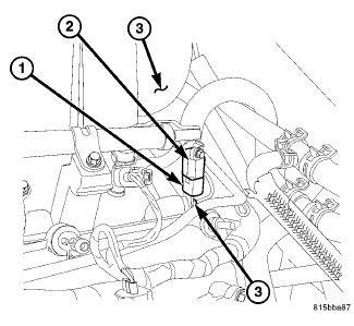
- Lubricate the Oil Control Valve (OCV) rubber O-ring seal with clean engine oil.
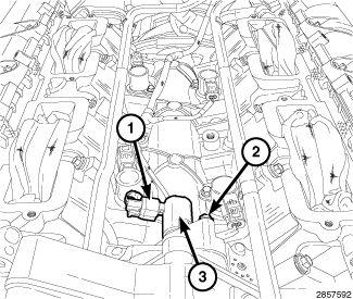
- Install the OCV (3) and rotate into position.
- Install the OCV retaining bolt (2) and tighten to the proper specification. Refer to TORQUE SPECIFICATIONS .
- Connect the OCV wire harness connector (1).
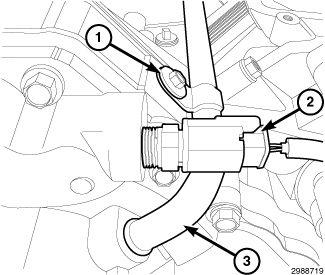
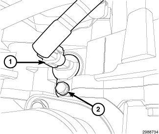
- Position the heater tube (3) into the water pump.
- Install the heater tube retaining bolt (1) and tighten to the proper specification. Refer to TORQUE SPECIFICATIONS .
- Connect the wire harness connector to the coolant temperature (ECT) sensor (2).
- Connect the camshaft position sensor wire harness connector (1).
- Install the intake manifold. Refer to
MANIFOLD, INTAKE, INSTALLATION .
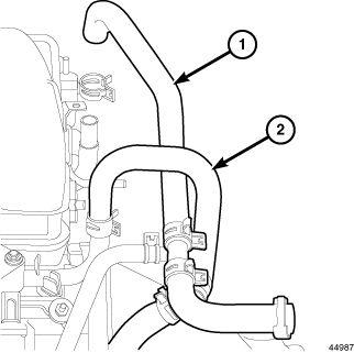
- Connect the heater hoses (1, 2).
- Connect the ground wires to the rear of each cylinder head.NOTE:
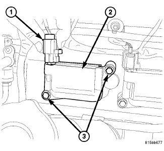
The ignition capacitor (2) is attached to the rear of the left cylinder head.
- Connect the ignition capacitor (2) wire harness connector (1).
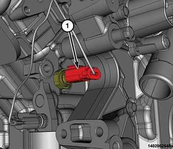
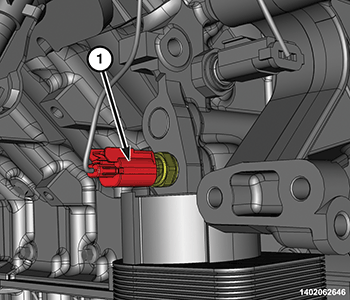
- Connect the oil pressure sensor wire harness connector (1).
- Connect the oil temperature sensor wire harness connector (1).
- Install the generator. Refer to GENERATOR, INSTALLATION, 5.7L AND 6.4L .
- Raise and support the vehicle.
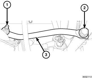
- Position the generator support bracket (3) to the engine mount, install the retaining nut (1) finger tight.
- Position the generator support bracket to the generator, install the retaining bolt (2) and tighten to the proper specification. Refer to TORQUE SPECIFICATIONS .
- Tighten the generator support bracket to engine mount retaining nut to the proper specification. Refer to TORQUE SPECIFICATIONS .
- Install the A/C compressor. Refer to COMPRESSOR, A/C, REMOVAL
.
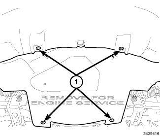
- Install the belly pan and securely tighten bolts (1).
- Remove support and lower the vehicle.
- Install the A/C liquid line. Refer to LINE, A/C LIQUID, INSTALLATION
.
- Position the ignition coil wire harness and connect all ignition coil wire harness connectors (1).
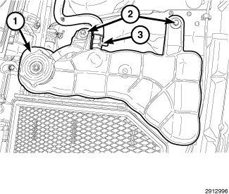
- Position the coolant bottle (1) and install the coolant bottle retaining bolts (2).
- Install the Power Distribution Center (PDC) mounting bracket.
- Install the PDC (Refer to DESCRIPTION .
- Position the wire harness and secure to the right hand inner fender panel.
- Install the cooling fan. Refer to FAN, COOLING, INSTALLATION, 6.4L DUAL FAN
.
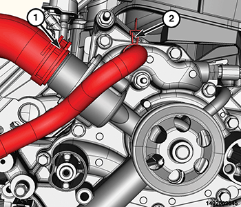
- Position the oil cooler hose and Install oil cooler hose clamp (2).
- Position the upper radiator hose and Install the upper radiator hose clamp (1).
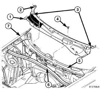
- Install the strut tower support (6) and tighten the bolts to the proper specification. Refer to TORQUE SPECIFICATIONS .
- Install the cowl panel cover (1). Refer to COVER, COWL PANEL, INSTALLATION .
- Install a NEW engine oil filter and fill the crankcase with the specified type and amount of engine oil. Refer to CAPACITIES AND RECOMMENDED FLUIDS, SPECIFICATIONS .
- Fill the cooling system with the specified type and amount of engine coolant. Refer to STANDARD PROCEDURE
.
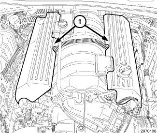
- Install the engine covers (1) onto the ball studs.
- Connect the negative battery cable.
- Perform the Refrigerant System Charge procedure. Refer to PLUMBING, STANDARD PROCEDURE .
- Start the engine and inspect for leaks.
The Cam/Crank Variation Relearn procedure must be performed using the scan tool anytime there has been a repair/replacement made to a powertrain system, for example: flywheel, valvetrain, camshaft and/or crankshaft sensors or components.