Section 5 (6.2L Engine (Service Information)): Removal
If the engine encounters a catastrophic failure, the engine oil cooler and lines must be replaced or damage to the new engine or components could result.
- Raise and support the vehicle. Refer to HOISTING, STANDARD PROCEDURE .
- Drain the cooling system. Refer to STANDARD PROCEDURE .
- Drain the engine oil. Refer to OIL .
- Remove the supercharger assembly. Refer to SUPERCHARGER, REMOVAL .
- Remove the cooling fan. Refer to 6.2L SINGLE FAN
.NOTE:
The power steering lines do not need to be removed from the pump. Position pump to the side.
- Remove the power steering pump. Refer to PUMP, REMOVAL .
- Remove the A/C compressor. Refer to COMPRESSOR, A/C, REMOVAL
.NOTE:
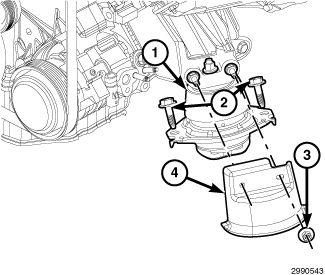
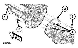
Left side shown, right side similar.
- Remove both left/right engine mount heat shield (4) retaining nuts (3) and remove the heat shields.
- Remove both left/right engine mount to frame retaining bolts (2).
- Disconnect the transmission oil cooler lines from their retainers at the oil pan.
- Remove the lower radiator hose.
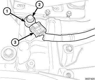
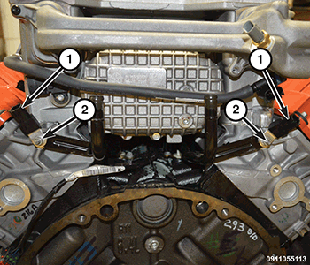
NOTE:Two knock sensors are used. Each sensor is bolted to the outside of the engine block below the exhaust manifold.
NOTE:Left side shown, right side similar.
- Remove the heat shields from both knock sensors (shield snaps on/off sensor).
- Disconnect the knock sensor electrical connectors (3).
- Remove both catalytic converters. Refer to CONVERTER, CATALYTIC, REMOVAL, 6.2L/6.4L
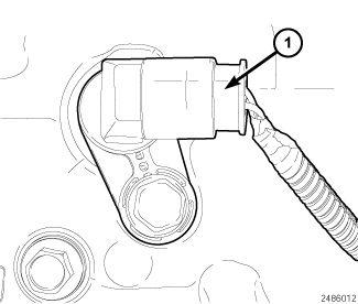
.NOTE:
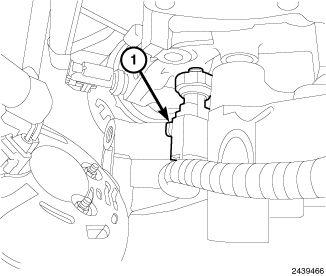
The Crankshaft Position (CKP) sensor is located at the right-rear side of the engine block.
- Remove the CKP sensor wire harness connector (1).
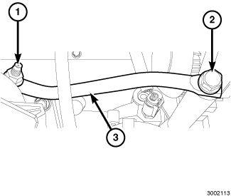
- Remove the generator support bracket to engine mount retaining nut (1).
- Remove the generator support bracket retaining bolt (2) and remove the support bracket (3).
- Lower the vehicle.
- Remove the generator. Refer to: GENERATOR, REMOVAL, 6.2L .
- Remove the A/C liquid line. Refer to LINE, A/C LIQUID, REMOVAL .
- Remove the A/C suction line. Refer to LINE, A/C SUCTION, REMOVAL
.
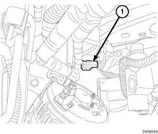
- Remove the oil pressure sensor electrical connector (1).
- Remove the oil temperature wire harness connector (1).
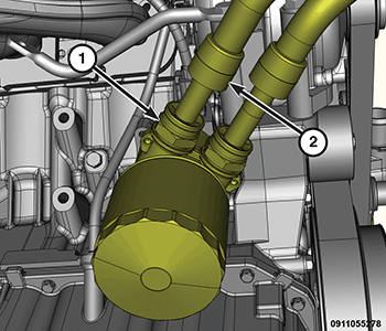
- Use a commercially available low profile 3/4" quick release tool to disconnect the oil filter adapter quick connectors (1) and then remove the oil cooler hoses (2) from the oil filter adapter.
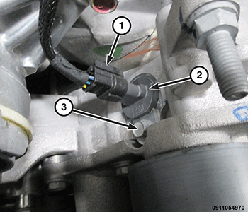
- Disconnect the camshaft position sensor (2) wire harness connector (1).
- Remove the heater hoses from the coolant tubes (1).
- Remove the Variable Valve Timing Solenoid (VVTS). Refer to SOLENOID, VARIABLE VALVE TIMING (VVTS), EXHAUST .
- Remove the pressurized coolant bottle. Refer to BOTTLE, PRESSURIZED COOLANT, REMOVAL
.
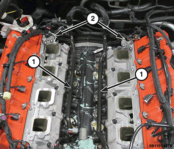
- Remove all ignition coil wire harness connectors (2) and position the harness aside.
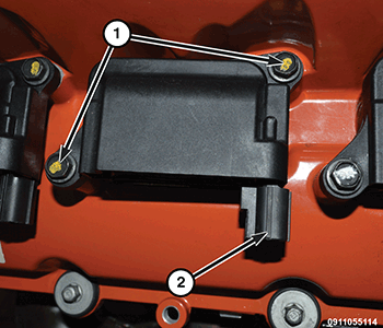
- Remove the ignition capacitor (2) wire harness connectors (1).
- Remove the ground wires from the rear of each cylinder head.
- For automatic transmission equipped vehicles, follow steps 34-40.
- Remove the starter. Refer to: STARTER, REMOVAL, 6.2L
.
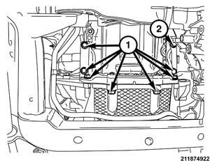
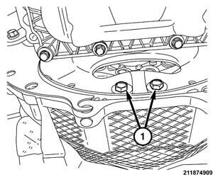
- Remove the transmission to engine structural cover retaining bolts (1) and remove the cover.NOTE:
The left front bolt (2) must be removed with the structural cover.
- Automatic transmission equipped vehicles, rotate the crankshaft in clockwise direction until the torque converter bolts (1) are accessible and remove the flexplate to torque converter bolts.
- Remove two engine to transmission bolts (3).
- Remove remaining transmission to engine bolts (4).CAUTION:
While carefully separating the engine from the transmission and removing the engine from the vehicle, constant checks must be made to ensure no damage to other components or wiring harnesses occur throughout the removal procedure.
- Lower the vehicle.
- Using a suitable jack, support the transmission.NOTE:
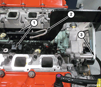
Do not use air tools to install engine lift fixture.
- Install the (special tool #8984B, Fixture, Engine Lifting) (1) and (special tool #2013800091, Adapter, Engine Lifting Bracket) (3).
- Using a suitable engine hoist, separate the engine from the transmission and remove the engine from the engine compartment.
- Secure the engine onto a suitable engine stand.